The wireless testbed refers to the toolchain that allows users to deploy custom firmware to the CC1310 (868MHz) and nRF52840 (2.4GHz) programmable radios incorporated into the hardware of the edge nodes, deployed along the A4174 in Bristol.
Below is the process of creating and uploading radio firmware to the testbed and creating an image to be deployed to the edges-node to gather, broadcast and optionally process data. Wireless experiments can include one or all of the edge nodes available on the network and are scheduled at a time and duration specified by the user.
The section summarises the actions to take to create an experiment, run and view the results using the UMBRELLA portal. It covers using the UMBRELLA portal to deploy both things to the edge nodes. Users can follow through this process with existing example firmware and experiment images.
Visit UMBRELLA Portal , Login, UMBRELLA HOME > Umbrella Networks
New Project > Enter Project Name, Description, Node Network (default, dummy Node Network) > Create Project
The Network section provides details about the different nodes available.
The Files section allows users to upload container images (running on Raspberry Pi and Jetson Nano) and Binary images (for nrf52 and cc1310).
Users can upload container images from a public repo (such as a docker registry or container registry) or a local file (.tar).
Containers shall perform all node data streaming operations via the MQTT broker hosted in the backend. Any software application requiring dataset transmission to the backend is responsible for the creation of its client, topic creation and publish rates.
A user will have to create a project before uploading a container. Doing so will produce a unique project ID.
The user will then be able to embed this project ID into their experiment source code for creating an MQTT topic in the following format. This container can be re-used between experiments, reporting to the same project-specific topic.
experiment/projectID/streamID/hostName
experiment: Fixed category prefix for all experiment-created topics. In the future, UMBRELLA may support many categories. experiment identifies the topic as experiment related.
projectID: Unique project ID code generated by the backend upon creating a project. projectID identifies the topic as related to a single specific project.
streamID: Integer data stream ID. Permits an experiment application to publish multiple topics. streamID identifies the topic related to a specific data stream within an experiment.
hostName: Unique per node. The user’s experiment will gather this at runtime from the software daemon. hostName identifies the topic as related to a unique host within an experiment.
Each subscription for a specific data stream shall require the user to define a JSON schema of the received data within the portal.
In the cases where the data stream ID is not specified, a data format cannot be ascertained; thus, the user will not be given the option to map data to a schema and, therefore, cannot be represented within the Grafana GUI.
Each subscription with a defined schema shall be capable of populating its influx database table, from which it shall be possible for a user to configure a Grafana dashboard of results by assigning one or more fields within the table to one or more Grafana GUI element.
The toolchain setup required to build radio firmware is described in the Contiki-NG Wiki, select the toolchain appropriate to the operating system (the development team at Toshiba use a native Linux installation).
Radio firmware for the UMBRELLA board can be created by cloning Contiki-NG and applying a patch on a specific commit. It is recommended that this is used as a starting point for newer users as Contiki-NG provides a well-documented software stack for both the CC1310 and nRF52840 SoCs, available on the UMBRELLA board.
Visit UMBRELLA Portal , Login, UMBRELLA HOME > Robotic Networks
New Project > Enter Project Name, Description, Arena (default, dummy Node Network) > Create Project
The Files section provides a user to upload container images (for running on Controller and Radio Simulator), configurations (for Configuration and World) and Binary images (for nrf52 and cc1310).
Users can upload container images from a public repo (such as a docker registry or container registry) or a local file (.tar).
Specify the duration of the experiment.
Validate experiment containers with the simulator to check that they are operating correctly, by running the experiments containers, together with a simulator container, using the real arena environment files.
Run the simulations.
Observe the progress through the Gazebo web view.
Results of the experiments are returned and displayed on the Umbrella portal interface.
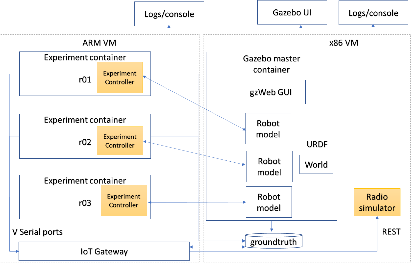
The digital twin setup and steps required for deployment are illustrated below. The ARM and X86_64 VM configurations supporting the digital twins run experiment containers in the same manner as the physical arena. Limiting the number of robot instances permitted (e.g. 120) to run in the simulator VM is possible. The main differences between the simulator and real arena deployments are that in the arena, the maximum number of robots is 20. An additional radio simulation container and configuration files are permitted per experiment in the simulator.
Digital twin simulator setup within Cloud EKS cluster
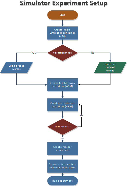
Flow for setting up simulation experiment in cloud VM
The experiment software will be deployed and interact with the simulator container in the same manner as the robot nodes (i.e. using ROSv2 and DDS). The portal allows uploading and setting the environment model, selecting the number of robot nodes from those available, and viewing the arena video and ground truth.
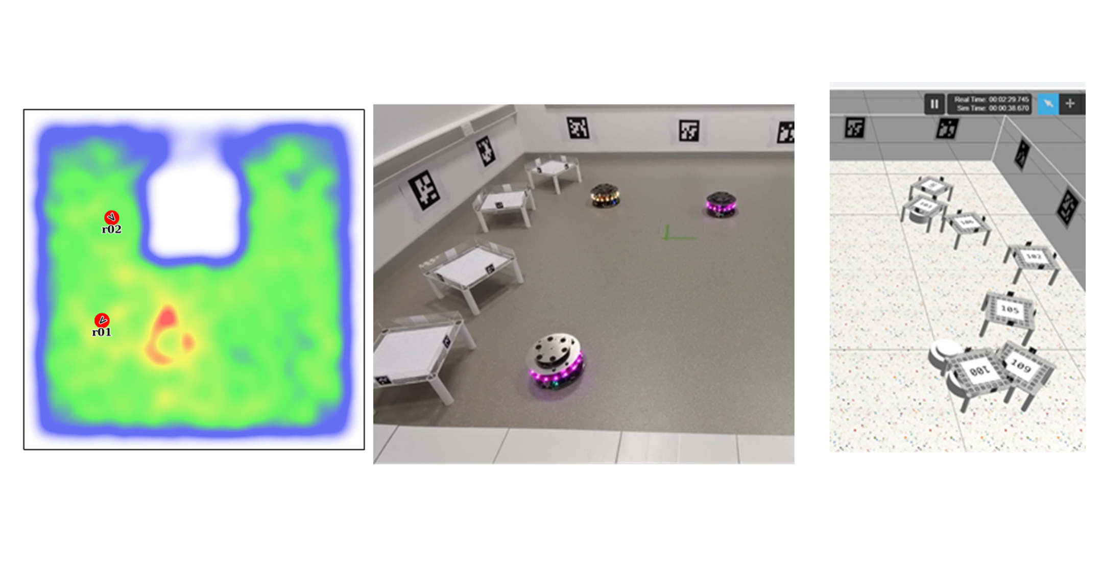
Ground truth map view (left) and simulator view (right)
The ROS2 bags and ground truth data are stored locally, which can be visualised or downloaded via the portal. It happens the same way in the real arena robot, but the main difference is obviously in a cloud VM environment.
The Gazebo web client interface is used only for visualising the GUI output of the simulator to the users within WebGL-compliant browsers. The association of experiment containers with simulator instances uses a separate Kubernetes cluster for each simulation instance.
Validate experiments before using the arena
The user can use the simulation environment first to validate an experiment. In validation mode, Users cannot override the world files. The experiment must complete successfully, without any robot or wall collisions, to be permitted to run in the arena. Once the experiment has been validated in the simulation environment, the user can run the experiment in the arena.
Experiment process
In both the simulation and arena environments, the experiment containers are deployed when the experiment starts. A first-in, first-out queue is used to schedule the start times.
After the experiment starts, the containers initialise and subscribe to the ROS2 topics.
In the simulator environment, the containers also need to spawn the robot model instance in the Gazebo simulator. Containers are passed the environment variable ROBOTSIM, whose value is true when running in the simulator.
The start position and orientation of the robot are passed as an environment variable ROBOTPOSE which provides the x and y coordinates from the centre reference and the orientation in radians. For example; 1.0,-1.0,0.5. In addition, the ROBOTID environment variable contains the friendly name of the robot instance. An additional environment variable called controllerOptions is passed to the experiment containers containing the controller option to run for the experiment.
The spawning of the robot models is performed using the following bootstrap code in the experiment container
When the user is running an experiment, ROS2 bags can be recorded in the experiment container /storage folder so that the user can download them after the experiment has been completed.
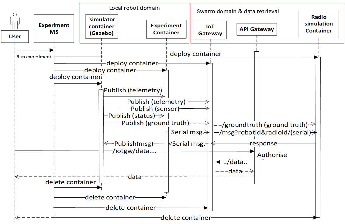
Message sequence diagram for the digital twin simulation is shown below:
The contents can include the ground truth odometry data that the user can use to evaluate the experiment. Video, ground truth or simulator visualisations are provided in the portal during the experiment. Users can cancel the experiment in the event of any unintended behaviour.
The user must build container images to create and run experiments in the physical robot arena and simulation environments.
We describe how to build the experiment Docker container images, with instructions for the robot simulator testbed, using an example Docker radio simulator container: timfa/radiosimulator:latest. Alternatively, the pre-built timfa/controller:base controller image can be used if only the main controller python files are being customised, as they can be loaded at runtime.
All container images are security scanned for vulnerabilities and must not be higher than a medium level to be permitted to run on the testbed.
The below example shows an experiment container with images that contain the robot controller code and utilise the ROS2 galactic release as the basis for accessing sensors, cameras, motors and actuators.
The example Dockerfile below is used to build the base experiment controller. The following Docker command builds and pushes the file to the Docker hub (using moby/buildkit:buildx-stable-1) : dockerbuildxbuild--platformlinux/arm64-t<containerimage>--push.
To build the file directly on an ARM64 node without cross-compiling it, use: dockerbuild-t<containerimage>. The image can be imported directly from the Docker hub into the robot simulator testbed.
The contents of the example timfa/dotstest:latest Dockerfile is as follows:
#------------------------------------------------------------------
# Use the  dots_project galactic image to build the package

    FROM simonj23/dots_project:galactic

    ENV USER=dots
    ENV DUID=1099
    ENV DGID=1099

    COPY docker/startup.sh /startup.sh
    RUN chmod +x /startup.sh

    ENV TERM=xterm-256color
    RUN mkdir -p /home/dots
    RUN cp /etc/skel/.bashrc /home/dots
    # Add a red bit to the prompt to show we're in a docker environment
    RUN sed -i 's/\(PS1.*00m\\\]:\)/\1\\[\\033[31m\\](in docker)/' /home/dots/.bashrc

    ENV ROS_DOMAIN_ID=0
    ENV CYCLONEDDS_URI=file:///config/cyclonedds_robots.xml

    COPY config /config

    RUN <<EOF cat >> /home/dots/.bashrc
    source /opt/ros/galactic/setup.bash
    source /dots_project/grid_map_ws/install/setup.bash
    source /dots_project/py_trees_ws/install/setup.bash
    EOF

    RUN groupadd -g $DGID $USER
    RUN useradd --shell /bin/bash --groups adm,sudo -u $DUID -g $DGID $USER
    WORKDIR /home/dots/dots_project
    ADD src src
    ADD scripts scripts

    WORKDIR /home/$USER/dots_project/src
    RUN bash -c 'colcon build --merge-install --packages-ignore \
    gazebo_dev  gazebo_plugins bagparse'
    RUN chmod +x /home/$USER/dots_project/src/install/share/dots_sim/launch/rsp_helper.sh
    RUN chmod a+rw /tmp

    ENTRYPOINT ["/startup.sh"]
When building a final controller image, the entry point command needs to be added, such as:
The experiment container contains the Robot controller.
The controller.launch.py is the Python code for the controller initialisation in this instance.
Note
if the logs need to be recorded for post-experiment analysis, they have been placed in the docker container’s /storage folder. The example below dumped the odom ROS2 topics into the /storage folder. The /<robotname>/odom topic contains the robot’s ground truth position and orientation data. In the simulation environment, the robot name is the friendly ROBOTID, as provided in the experiment configuration on the portal. However, in the arena deployment, the physical robot hostname, with a hyphen replaced by an underscore, is used for the name, which is umbrella_<robotidhash>.
controller.launch.py
importosfromament_index_python.packagesimportget_package_share_directoryfromlaunchimportLaunchDescriptionfromlaunch_ros.actionsimportNodefromlaunch.actionsimportExecuteProcess,IncludeLaunchDescriptionfromlaunch.actionsimportDeclareLaunchArgumentfromlaunch.substitutionsimportLaunchConfigurationfromlaunch.launch_description_sourcesimportPythonLaunchDescriptionSource,FrontendLaunchDescriptionSourcedefgenerate_launch_description():pkg_share=get_package_share_directory('dots_example_controller')controller_option=LaunchConfiguration('controllerOptions')use_sim_time=LaunchConfiguration('use_sim_time')robot_name=LaunchConfiguration('robot_name')declare_use_sim_time=DeclareLaunchArgument('use_sim_time',default_value='true')declare_robot_name=DeclareLaunchArgument('robot_name',default_value='robot_deadbeef')setup_cmd=IncludeLaunchDescription(PythonLaunchDescriptionSource(os.path.join(pkg_share,'launch','basic_cam.launch.py')),)#---------------------------------------------------------------------------# CONTROLLER OPTION HAS YOUR CONTOLLER#---------------------------------------------------------------------------controller_cmd=Node(package='dots_example_controller',executable=controller_option,namespace=robot_name,output='screen',parameters=[{'use_sim_time':use_sim_time}])#---------------------------------------------------------------------------# Build the launch descriptionld=LaunchDescription()bag_name=os.environ.get('ROBOTID')ld.add_entity(ExecuteProcess(cmd=['ros2','bag','record','--compression-mode','file','--compression-format','zstd',#'--qos-profile-overrides-path', 'override.yaml','-o','/storage/%s'%bag_name,'/%s/odom'%bag_name.replace("-0","")],output='screen'))ld.add_action(declare_use_sim_time)ld.add_action(declare_robot_name)ld.add_action(setup_cmd)ld.add_action(controller_cmd)returnld
Users can define their radio simulators to run on the testbed platform. It uses the virtual serial port redirection to emulate the radios. These are exposed in the controller containers as serial ports, which can be used with ROS2 over serial code examples.
The COBS encapsulation can be used to delimit the messages intercepted and redirected to the radio simulator container. The radio simulator containers expose HTTP port 80 as a REST API to emulate the radio performance. The REST API definition for the radio serial port redirected messages /msg is called each time a message is redirected from a specific serial port on each robot.
The response contains the recipients of the message and the corresponding performance:
"/msg":{"post":{"description":“Redirected messages to the simulator","parameters":[{"name":"experimentid","in":"query","required":false,"style":"form","explode":true,"schema":{"type":"string"}},{"name":"robotid","in":"query","required":false,"style":"form","explode":true,"schema":{"type":"string"}},{"name":"radioid","in":"query","required":false,"style":"form","explode":true,"schema":{"type":"string"}}],"requestBody":{"content":{"application/octet-stream":{"schema":{"type":"object"}}},"required":false},"responses":{"200":{"description":"ReturnstheJSONobjectwithradioperformance"}},"security":[{"default":[]}]}
The JSON result object specifies the latency (in ms) and the success rate for each destination radio corresponding to the robots. An example of the JSON return data is:
In addition, the /groundtruth API permits the periodic updating of the ground truth data with the radio simulator. The update rate is specified in the experiment configuration file. The radio simulator /groundtruth API is then called at this rate. Note that the update rate is in real time rather than simulator time. Simulation time is encapsulated in the sec and nano sec parameters in the time stamp object of the ground truth JSON.
"/groundtruth":{"post":{"description":"Update the ground truth robot position and orientation data","parameters":[{"name":"experimentid","in":"query","required":false,"style":"form","explode":true,"schema":{"type":"string"}}],"requestBody":{"content":{"application/json":{"schema":{"type":"object"}}},"required":false},"responses":{"200":{"description":"ok"}},"security":[{"default":[]}]}
The ground truth contains an array of groundtruth data corresponding to each robot or other object. The data includes the odometry elements for each object. An example JSON groundtruth object is:
The following example is a radio simulator controller written in C#. This can be encapsulated in a container using the aspnet:3.1-focalbase to permit deployment in Linux containers. This is supported in Visual Studio 2019 version 16.11 and above. The radio simulator listens on HTTP port 80 and serves the REST APIs for controlling the serial port message redirects. It also optionally serves the Controller python scripts if the controller content is placed in the project’s content directory. In this way, it is only necessary to update the single container when testing new controllers and radio algorithms.
usingSystem;usingSystem.Collections.Generic;usingSystem.Diagnostics;usingSystem.Linq;usingSystem.Threading.Tasks;usingMicrosoft.AspNetCore.Mvc;usingMicrosoft.Extensions.Logging;usingRadioSimulator.Models;namespaceRadioSimulator.Controllers{//Position and orientation coordinates//Position in cartersian and orientation in quaternionpublicclassPosition{// coordinates in metres from origin (centre)publicfloatx{get;set;}publicfloaty{get;set;}publicfloatz{get;set;}}publicclassOrientation{// Orientation in Quaternion radianspublicfloatx{get;set;}publicfloaty{get;set;}publicfloatz{get;set;}publicfloatw{get;set;}}publicclassPose{// Pose consisting of position and orientationpublicPositionposition{get;set;}publicOrientationorientation{get;set;}}publicclassPoseHolder{publicPosepose{get;set;}}publicclassStamp{// Timestamppublicintsec{get;set;}publicintnanosec{get;set;}}publicclassHeader{publicstringframe_id{get;set;}publicStampstamp{get;set;}}//Ground Truth Data StructurepublicclassGTData{publicstringobject_id{get;set;}publicHeaderheader{get;set;}publicstringchild_frame_id{get;set;}publicPoseHolderpose{get;set;}}publicclassGTRequest{publicGTData[]groundtruth{get;set;}}publicclassRadio{publicstringid{get;set;}publicdoublelatency{get;set;}publicdoublesuccessrate{get;set;}}publicclassRobot{publicstringid{get;set;}publicRadio[]radio{get;set;}}publicclasssimResponse{publicRobot[]robot{get;set;}}publicclassError{publicstringmessage{get;set;}}//Main controller classpublicclassHomeController:Controller{privatereadonlyILogger<HomeController>_logger;privatestaticGTRequestgtCache=null;publicHomeController(ILogger<HomeController>logger){_logger=logger;}publicIActionResultIndex(){returnView();}publicIActionResultPrivacy(){returnView();}[ResponseCache(Duration = 0, Location = ResponseCacheLocation.None, NoStore = true)]publicIActionResultError(){returnView(newErrorViewModel{RequestId=Activity.Current?.Id??HttpContext.TraceIdentifier});}[HttpPost("msg/")]publicJsonResultPostMsg([FromQuery]stringexperimentid,[FromQuery]stringrobotid,[FromQuery]stringradioid){if(gtCache==null){Errorerror=newError();error.message="No ground truth data available";returnJson(error);}simResponsesimResponse=newsimResponse();simResponse.robot=newRobot[gtCache.groundtruth.Length];for(introbot=0;robot<gtCache.groundtruth.Length;robot++){simResponse.robot[robot]=newRobot();simResponse.robot[robot].id=gtCache.groundtruth[robot].object_id;simResponse.robot[robot].radio=newRadio[1];simResponse.robot[robot].radio[0]=newRadio();simResponse.robot[robot].radio[0].id=radioid;simResponse.robot[robot].radio[0].latency=0;simResponse.robot[robot].radio[0].successrate=1;}returnJson(simResponse);}[HttpPost("groundtruth/")]publicActionResult<string>PostGT([FromBody]GTRequestgtData,[FromQuery]stringexperimentid){gtCache=gtData;return("ok");}}}
Example Docker file to build the radio simulator experiment container image
Users can obtain the example image from timfa/radiosimulator:latest Note that the ubuntu base images need to be used to avoid image vulnerability issues.
#------------------------------------------------------------------# Radio Simulator Controller example - experiment containerFROMmcr.microsoft.com/dotnet/aspnet:3.1-focalASbaseRUNapt-yupdate&&apt-get-yupgrade
WORKDIR/appEXPOSE80FROMmcr.microsoft.com/dotnet/core/sdk:3.1-focalASbuildWORKDIR/srcCOPY["RadioSimulator/RadioSimulator.csproj","RadioSimulator/"]RUNdotnetrestore"RadioSimulator/RadioSimulator.csproj"COPY..
WORKDIR"/src/RadioSimulator"RUNdotnetbuild"RadioSimulator.csproj"-cRelease-o/app/build
FROMbuildASpublishRUNdotnetpublish"RadioSimulator.csproj"-cRelease-o/app/publish
FROMbaseASfinalWORKDIR/appCOPY--from=publish/app/publish.
ENTRYPOINT["dotnet","RadioSimulator.dll"]
Configuration files are used to run the experiment.
Below is an example of a configuration file to run experiments in the physical robotics arena and simulations. The configuration options are passed to the controller and gazebo containers at the startup of the simulation.
The robotPreferences section describes the start position and orientation of the robot instances and is passed in ROBOTPOSE and ROBOTID variables.
The controllerOptions environment variable is passed to all the controller containers that permit loading different controller configurations.
The gazeboOptions variable is passed to the Gazebo container and consists of the delivery order and manual start flags separated by the dash (-).
The UPDATERATE variable is used for simulation time step control, and the delimiter is the serial port message delimiter required for passing messages to the radio simulator for emulation of the radio devices where the radio devices in use are mapped to serial ports (/dev/ttyACMX) using the radios list, with X denoted by the radio index.
World files are used in simulation experiments to define the configuration of the environment of the test. Using SDF, create world files with the configuration required for the experiment.
The LoRa Network for the UMBRELLA project refers to the Chirpstack Network Server running on the UMBRELLA backend and a subset of UMBRELLA nodes that act as gateways. The webpages the user interacts with are wrappers around the Chirpstack API to provide continuity between UMBRELLA platforms.
The section will explain to the user the process of creating LoRaWAN Applications in UMBRELLA - quirks to be aware of etc. This guide will not seek to explain LoRaWAN, for which there is much better documentation. External links to Chirpstack pages will also be provided where appropriate, as most of the user interface and naming remain unchanged.
The contents of this section are described below and should be followed through in sequential order for users seeking to create new LoRaWAN applications.
Organisations are used within Chirpstack. to provide separate environments for different groups of users, allowing them to configure their devices and add their applications.
This guide will discuss the process of building the example for a B-L072Z-LRWAN1 LoRa®/Sigfox™ Discovery kit, this can be bought from a number of suppliers in the UK. This guide is aimed at users who are newer to LoRaWAN and would otherwise struggle with setting a device up and interpreting datasheets.
Alternatively - LoRaWAN is supported by many commercial off-the-shelf devices, so feel free to buy something that fits the needs. Please contact us if you’d like more information on the gateways we use and compatibility.
It is useful to install a serial terminal program to more easily inspect the logs from firmware builds. I have used Picocom. In order to install this on a Debian-based Linux distribution. First, ensure your repo list is up to date, run:
Here we describe how to build the LoRaWAN sample firmware when using the Zephyr repository.
$ cd<repo_location>/zephyrproject/zephyr/samples/subsys/lorawan/class_a
##When listing files in the directory - the user should see the following$ ls
CMakeLists.txt prj.conf sample.yaml src
In order for this to work with the UMBRELLA network - it needs the following modification to the prj.conf file. Change yours to reflect what is shown below - without this modification the firmware will operate with incorrect regional parameters (it would not work).
When this change has been made we can build the firmware.
$ westbuild-bb_l072z_lrwan1
If successful, the command should return something like this:
(.venv)ingram@ubuntu:~/zephyrproject/zephyr/samples/subsys/lorawan/class_a$ westbuild-bb_l072z_lrwan1
-- west build: generating a build systemLoading Zephyr default modules (Zephyr base).-- Application: /home/ingram/zephyrproject/zephyr/samples/subsys/lorawan/class_a-- Found Python3: /home/ingram/zephyrproject/.venv/bin/python3 (found suitable exact version "3.8.10") found components: Interpreter-- Cache files will be written to: /home/ingram/.cache/zephyr-- Zephyr version: 3.2.99 (/home/ingram/zephyrproject/zephyr)-- Found west (found suitable version "0.14.0", minimum required is "0.7.1")-- Board: b_l072z_lrwan1-- ZEPHYR_TOOLCHAIN_VARIANT not set, trying to locate Zephyr SDK-- Found host-tools: zephyr 0.15.1 (/home/ingram/zephyr-sdk-0.15.1)-- Found toolchain: zephyr 0.15.1 (/home/ingram/zephyr-sdk-0.15.1)-- Found Dtc: /home/ingram/zephyr-sdk-0.15.1/sysroots/x86_64-pokysdk-linux/usr/bin/dtc (found suitable version "1.6.0", minimum required is "1.4.6")-- Found BOARD.dts: /home/ingram/zephyrproject/zephyr/boards/arm/b_l072z_lrwan1/b_l072z_lrwan1.dts-- Generated zephyr.dts: /home/ingram/zephyrproject/zephyr/samples/subsys/lorawan/class_a/build/zephyr/zephyr.dts-- Generated devicetree_generated.h: /home/ingram/zephyrproject/zephyr/samples/subsys/lorawan/class_a/build/zephyr/include/generated/devicetree_generated.h-- Including generated dts.cmake file: /home/ingram/zephyrproject/zephyr/samples/subsys/lorawan/class_a/build/zephyr/dts.cmakeParsing /home/ingram/zephyrproject/zephyr/KconfigLoaded configuration '/home/ingram/zephyrproject/zephyr/boards/arm/b_l072z_lrwan1/b_l072z_lrwan1_defconfig'Merged configuration '/home/ingram/zephyrproject/zephyr/samples/subsys/lorawan/class_a/prj.conf'Configuration saved to '/home/ingram/zephyrproject/zephyr/samples/subsys/lorawan/class_a/build/zephyr/.config'Kconfig header saved to '/home/ingram/zephyrproject/zephyr/samples/subsys/lorawan/class_a/build/zephyr/include/generated/autoconf.h'-- The C compiler identification is GNU 12.1.0-- The CXX compiler identification is GNU 12.1.0-- The ASM compiler identification is GNU-- Found assembler: /home/ingram/zephyr-sdk-0.15.1/arm-zephyr-eabi/bin/arm-zephyr-eabi-gcc-- Configuring done-- Generating done-- Build files have been written to: /home/ingram/zephyrproject/zephyr/samples/subsys/lorawan/class_a/build-- west build: building application[1/171] Preparing syscall dependency handling[3/171] Generating include/generated/version.h-- Zephyr version: 3.2.99 (/home/ingram/zephyrproject/zephyr), build: zephyr-v3.2.0-1003-g4b1585c23faf[161/171] Linking C executable zephyr/zephyr_pre0.elf[165/171] Linking C executable zephyr/zephyr_pre1.elf[171/171] Linking C executable zephyr/zephyr.elfMemory region Used Size Region Size %age Used FLASH: 74560 B 192 KB 37.92% RAM: 14064 B 20 KB 68.67% IDT_LIST: 0 GB 2 KB 0.00%(.venv)ingram@ubuntu:~/zephyrproject/zephyr/samples/subsys/lorawan/class_a$
We can then flash the firmware, provided the board if connected correctly to the machine. As with the blinky example successfully flashed earlier, the command is as follows:
On the Applications tab, CreateApplication to bring up the window as shown in the image below. Name your Application something descriptive and add something more descriptive for the description. Select the Service Profile you created earlier and create the Application.
Service profiles allow users to optionally add things such as Gateway Metadata to their payloads sent to the application server. The configuration of Service Profiles is documented here.
Device profiles are ways of managing different LoRaWAN device types within an Organisation. It allows new devices to be associated with a specific LoRaWAN profile rather than requiring configuration from scratch each time a similar device is added to an application (project). The details pertinent to a given device profile will be the configured attributes within the LoRaWAN stack used on the end device and things such as approximate uplink time.
Additionally, the device profile provides the user with a codec for sending and receiving data to the end device.
Once we have configured the device and data is coming into the portal, we need integrations to store the data. Integrations allow the user to push received data onto a third-party service for storage. The integrations supported by UMBRELLA are posting the data to an HTTP URL or integration with InfluxDB.
A json map of sensor data for a sensor restricted to the client by Admin
{"alertMessage":"You are not allowed to query these Sensors : BME680","data":[[{"sensorName":"Noise","parameters":["Max_bin_db","Max_bin_frequency","Noise_db"],"nodeDetails":[{"nodeId":"RSE-1-C","timeStamp":["2022-01-05T00:00:10.462Z","2022-01-05T00:01:10.482Z"],"values":{"Max_bin_db":[55.064575,63.432755,60.34762],"Max_bin_frequency":[254.0,254.0],"Noise_db":[43.49276,43.517883,41.589684]}},{"nodeId":"RSE-16-C","timeStamp":["2022-01-05T00:00:40.993Z","2022-01-05T00:01:41.089Z","2022-01-05T00:02:41.134Z"],"values":{"Max_bin_db":[66.90102,64.02167],"Max_bin_frequency":[254.0,508.0],"Noise_db":[50.653976,53.073746]}}]}],[{"sensorName":"Dust","parameters":["Pm10_ug_m3","Pm2_5_ug_m3"],"nodeDetails":[{"nodeId":"RSE-1-C","timeStamp":["2022-01-05T00:00:09.3Z","2022-01-05T00:01:09.404Z","2022-01-05T00:02:09.512Z"],"values":{"Pm10_ug_m3":[1.0,1.0,1.0],"Pm2_5_ug_m3":[1.0,1.0,0.0]}},{"nodeId":"RSE-16-C","timeStamp":["2022-01-05T00:00:39.912Z","2022-01-05T00:01:40.024Z"],"values":{"Pm10_ug_m3":[12.0,13.0],"Pm2_5_ug_m3":[4.0,4.0]}}]}]]}